
Additional OCP Networks
The Openshift documentation describes many different methods to add additional networks to your cluster. There are lots of options and sometimes these options overlap (many different ways to accomplish same task) and other times, only one method of adding the additional network may be supported based on the type of networking hardware (SR-IOV card is one example) that is being used.
When deciding which method to use, a question you may need to ask yourself is whether the additional networks are only needed for internal communication between two workloads (IE: pods) or if the additional network needs to expose an application to be reachable outside of the cluster. In the latter-case, exposing the workload can happen via another ingress/route (internal load balancer), a NodePort, external IP resource, or using the MetalLB Operator.
Additional networks can mean defining an additional VLAN on the primary NIC card on a control-plane node (not a common use-case) or using additional NIC cards on the control plane/worker nodes (including SR-IOV cards). These different NIC cards/networks may have varying characteristics including throughput requirements (1Gbps/10Gbps/etc) and may need to be segmented from other networks (IE: control-plane/upstream/Internet) due to security needs.
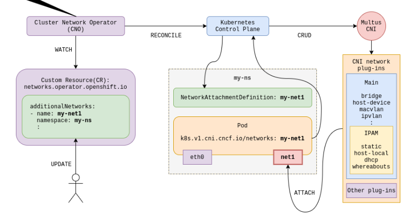
The Multus CNI is an umbrella term that is used to describe the attaching of multiple networks to pods. More information on this can be found at the following link:
 k8snetworkplumbingwg
I will use some of the official Openshift documentation (OCP 4.10) that describes the different ways additional networks can be implemented throughout this article.
Here is a layout of the information that will be covered:
- CNI Plugins that OCP uses for creating the additional networks.
- Tooling (operators) that can be used to configure network hardware and networking stack on control-plane/worker nodes to support additional networks on OCP.
- Exposing these additional networks outside of cluster
- Some exercises based on these concepts
CNI Plugins
First, I will show the different CNI (Container Network Interface) plugins that can be used.

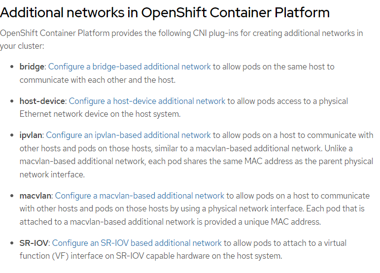
To further explain some of these top concepts some more, here are some of my own definitions:
Bridge- Typically this takes a physical network device (IE: NIC) and turns into a switch. In a traditional sense , the bridge can be used to host multiple virtual machines (IE: Libvirt/KVM). This same concept appliesin the container-world allowing OCP pods to connect to this bridge. Two modes of attaching pods to this bridge are supported in OCP (either ipvlan or macvlan). More on these two terms next.
HOST-DEVICE- This refers to any network device that is presented to the CoreOS (control-plane/worker) operating system.
IPVLAN- Each pod would have its own IP address but share the MAC address of the parent (physical NIC). This is typically used in situations where an upstream switch does not allow multiple mac addresses or there is a security limitation on the number of macs that an upstream switch will accept due to security policies. Unless this concern exists, typically MACVLAN is used. IPVLAN (typically as l3 mode) typically adds some more complexity as there is a virtual router between each of the sub-interfaces (pods). In some cases, this overhead is not the best performance-wise.
MACVLAN- Each pod has its own virtual mac address and IP address. For the most part, this mode is used due to the limitations expressed above with IPVLAN. One advantage with this method is if a DHCP server exists on the network. In this case, an IP address can automatically be assigned to the pod based on the unique mac address of the sub-interface.
If your network doesn't have a DHCP server, there are features of OCP/Kubernetes that can dynamically assign IP addresses using the IPAM (IP Address Management) CNI Plugin and WhereAbouts. These 2 features will be used in tandem at the end of the training exercise.
SR-IOV- More on this below (tooling section).
Tooling
Next, I will describe some of the tooling (mostly operators) that will be used to configure these additional networks.
The NMState Operator can be used to create the bridge or host-device (IE: NIC card) using NetworkManager tooling. This is the same tooling that is used on Linux-based operating systems to configure network-settings at the operating system level. With the NMState Operator, the operating systems of the control-plane/worker nodes is modified using the OCP platform (either through OC commands or web console).
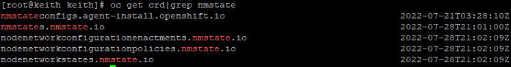
When installing the NMState Operator, a few different custom-resource-definitions are created. To see a list, run the following command:
oc get crd|grep nmstateThe output will look similar to below:
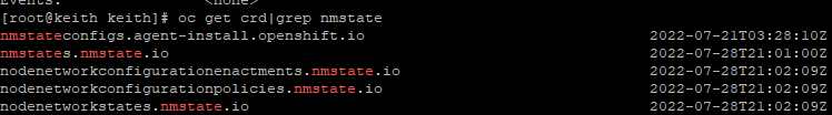
Without adding any additional settings, the only crd that will be populated is the nodenetworkstate. An object/definition for each of the OCP nodes will be generated. In it, you will see all of the network settings that were set at build-time of the cluster.
To see this information, run:
oc get nodenetworkstate
# Here you will an object for each node in the cluster
# Target one of the nodes to view details of nodenetworkstate
# One of my OCP nodes is called master-worker1
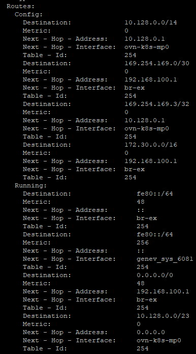
oc describe nodenetworkstate master-worker1Here you will see information on the node that was autoconfigured. In this case, my nodes used DHCP.

Here are some routes that are automatically created as well. A lot of these settings are the result of OpenVswitch/OVN configuration during the OCP install.
In the exercises below, we will work with the NMState tooling some more. In some cases, NetworkAttachmentDefinitions or making modifications through the ClusterNetworkOperator definitions is the preferred method for adding additional devices. It can be a little confusing having all of these different options to accomplish some of the same tasks. Here are some things I consider when using one method or the other.
- In most cases, use NMState Operator to configure settings that will be different on one node versus the other. For example, if you want to set a static IP address for an interface on each node, use NMState. On the other-hand, let's assume each OCP node has an eth1 interface and it will use DHCP for IP assignment. In this case, you can use an individual NetworkAttachmentDefinition or by making modifications to the ClusterNetworkOperator.
- Using the ClusterNetworkOperator is good if you want to apply a setting at cluster-install time but can also be used afterwards. The result of adding these settings to the ClusterNetworkOperator results in individual NetworkAttachmentDefinitions anyway.
- According to the OCP documentation, use individual NetworkAttachmentDefinitions in the cases when you want to chain multiple CNI plugins. I would assume it easier to have a more granular listing of NetworkAttachmentDefinitions instead of having everything defined at the cluster-level (ClusterNetworkOperator)?
The SR-IOV (Single Root I/O Virtualization) Operator takes a single network device and presents it as different virtual functions (multiple NICs) inside the control-plane/worker nodes' operating systems, thus allowing pods inside of OCP to consume these resources. One example of having multiple virtual functions would be to have different VLAN/IP address assignments to pods based on specific virtual function being attached. SR-IOV effectively takes one network card and virtualizes it.
I won't get as much into SR-IOV in this article due to limitations with the hardware in my home lab (I don't have any supported SR-IOV cards). There is plenty of other material to present and I may do a follow-on article on SR-IOV later if I acquire an SR-IOV capable card that is supported by OCP.
For the currently supported SR-IOV cards, see the following link
https://access.redhat.com/articles/6954499
Exposing Resources (Pods) Based on Additional Networks
The default ingress/route (*.apps.<clustername>.<domain>) that is installed with OCP is typically based on the network connection on the control-plane/worker node Machine Network. Depending on the install method of the OCP cluster, there is either a floating IP (with IPI install method) that automatically is put in front of all nodes that run workloads (workers) or a manual proxy configuration (Nginx or HAPROXY) that is placed in front of ports 80 (http) or 443 (https) for the routing of web-based traffic in the cluster.
When creating workloads that need to be accessible externally from the cluster that are on other interfaces/networks other than the Machine Network (ControlPlane/Worker), let's think about the limitations of Kubernetes/OCP and the your requirements for presenting/exposing those workloads.
In the Openshift documentation, there are a few methods that are described in great detail on exposing workloads. These workloads can either be exposed at the pod-level or through the OCP/Kubernetes service.
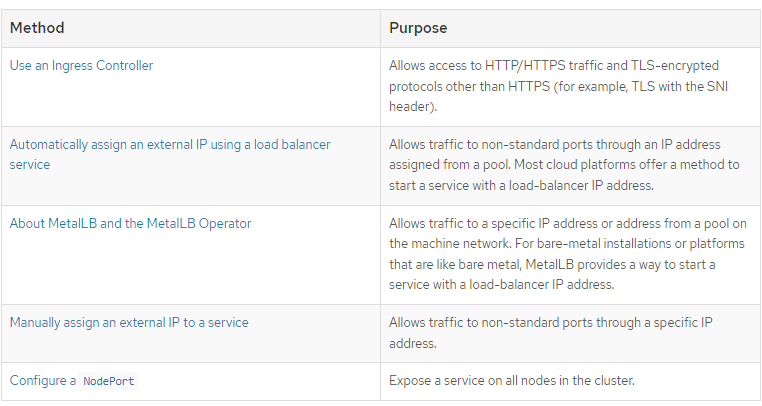
I will explain these terms in my own words.
NodePort- Binds a service/workload to a specific TCP port on all nodes in the cluster.
Ingress Controller - By default, when an OCP cluster is instantiated, there is a default IngressController defined in the openshift-ingress-operator namespace called default.
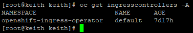
This default IngressController targets router pods (based on HAPROXY) that run in the openshift-ingress namespace. They use the HostNetwork endpoint publishing policy which uses NodePorts on two of the worker nodes (router replicaset is set to two by default). Any routes that are defined in the cluster (whether *.apps or custom-domain name) use this ingress by default.
My definition of Ingress/Route is a simplification for now. There may be a follow-on post later with more details.
MetalLB- This is similar to the load-balancer that gets automatically installed by OCP with IPI and most Assisted Installer methods of deployment. A floating IP from the Machine Network is assigned (from a pool). This is used mostly with bare-metal type deployments (non-IPI).
ExternalIP- This is similar to MetalLB but used primary with cloud providers which will automatically create a load-balancer resource based on the cloud-platform provider (IE: AWS Elastic Load Balancing).
Exercises
For reference, there will be 3 NIC cards on my OCP nodes. One is the primary NIC used on the Machine Network (enp1s0), the second one will be configured with a static IP on each of the nodes (enp7s0) using the NMState Operator. The third NIC will be setup in a bridge configuration (enp8s0).
My control-plane/worker (Machine Network) is 192.168.100.0/24 network.
In this exercise, the following actions will be performed.
- The NMState Operator will be installed.
- I will add an IP address configuration for an additional NIC card that is installed on each of the OCP nodes to show how to monitor/troubleshoot that process. This use-case may be appropriate if you want to assign a NodePort resource to the additional network/subnet that is attached to the enp7s0 interface. This network will be the 192.168.150.0/24 and non-routable (unreachable from my Machine Network).
- A bridge will be setup using the NetworkAttachmentDefinition CRD on enp8s0. A MACVLAN CNI will be used with dynamic IP provisioning (IPAM/Whereabouts)
- An httpd pod will be created and will be automatically assigned an IP address from the IPAM/Whereabouts pool.
- I will ping and run a curl command from one of the OCP nodes to confirm that the pod is responding.
Installation of NMState Operator
- From the Openshift Web Console, go to OperatorHub and search for NMState.
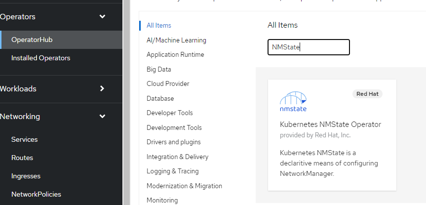
2. Click on NMState Operator and choose install.
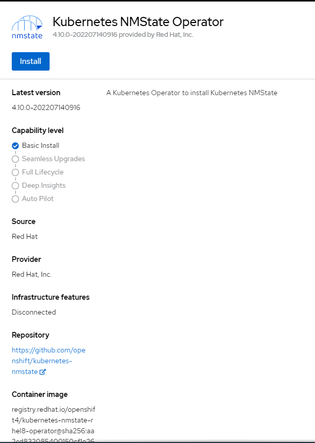
3. Accept the defaults. A namespace called openshift-nmstate will be used.
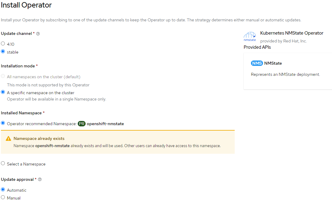
4. Choose install
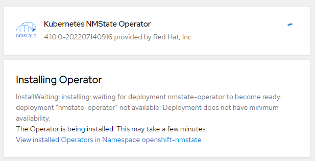
5. Wait for the status to change to green and the status to change to ready to use.
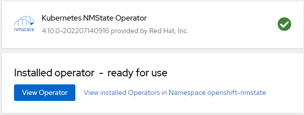
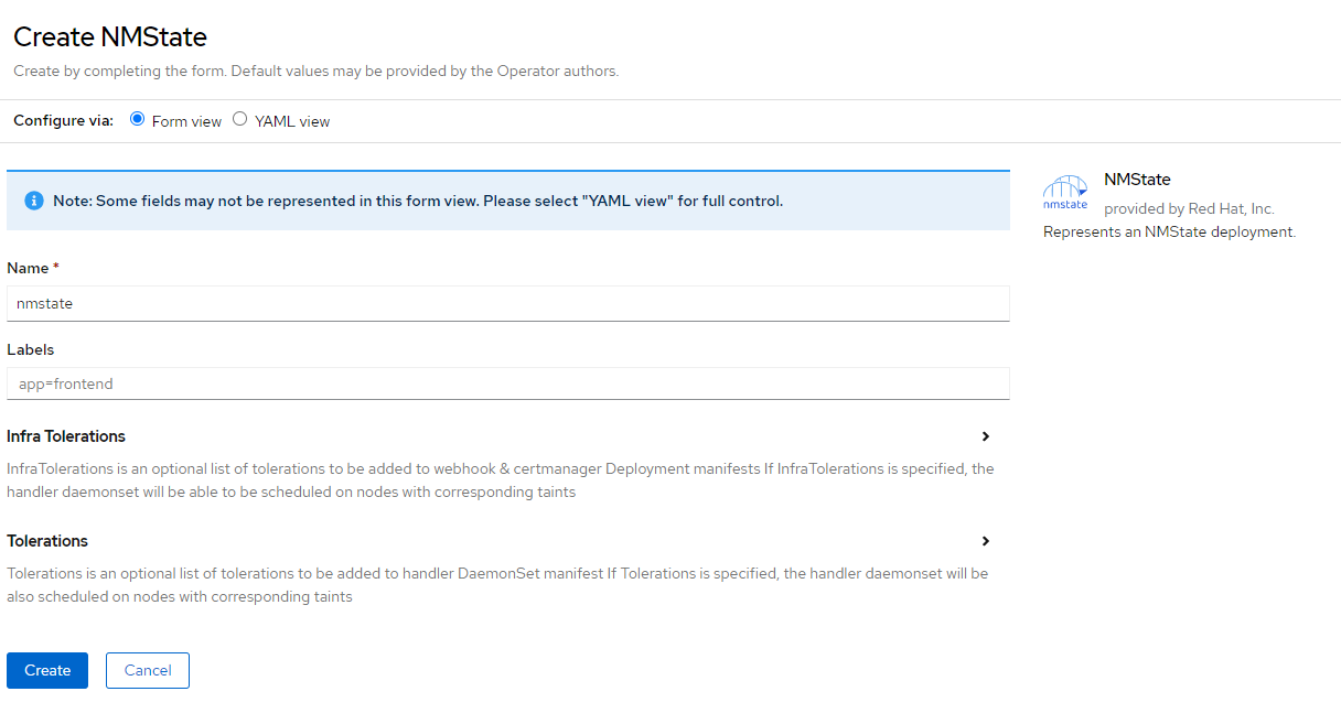
6. Next, let's create an NMSTATE instance.
7. On the oc command-line, run the following to verify that operator was successfully installed. This shows the CRDs that are exposed when this operator was installed.
oc get crd|grep nmstateVerify the output looks similar to this output
Using NMState Operator to Assign IP Address to eth1 on one of the OCP nodes
On my OCP node called master-worker1, I will add an IP address with no gateway to the 192.168.150.0/24 network using interface enp7s0. The IP will be 192.168.150.2.
Here is the NetworkAttachmentDefinition that will be used. The filename is master-worker1-nmstate-enp7s0.yaml:
apiVersion: nmstate.io/v1
kind: NodeNetworkConfigurationPolicy
metadata:
  name: enp7s0-policy-master-worker1
spec:
  nodeSelector:
    kubernetes.io/hostname: master-worker1
  desiredState:
    interfaces:
    - name: enp7s0
      description: Configuring enp7s0 on master-worker1
      type: ethernet
      state: up
      ipv4:
        address:
        - ip: 192.168.150.2
          prefix-length: 24
        enabled: true
        dhcp: false
Let's apply this definition
oc apply -f master-worker1-nmstate-enp7s0.yamlWhen this definition is applied, let's check a few things:
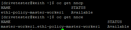
# To get list of policies that are applied
oc get nncp
# To get status on application of policies/enactments
oc get nnce
Both outputs below show successful configuration
As a final confirmation, we can do the following:
# Login to the node through OCP
oc debug node/master-worker1
# chroot /host when prompt appears
chroot /host
# Check for existence of IP on enp7s0
ip a|grep 192.168.150.2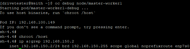
Let's apply the same configuration the last 2 nodes (master-worker2 and master-worker3). master-worker2 will have 192.168.150.3 IP and master-worker3 will have 192.168.150.4.
apiVersion: nmstate.io/v1
kind: NodeNetworkConfigurationPolicy
metadata:
  name: enp7s0-policy-master-worker2
spec:
  nodeSelector:
    kubernetes.io/hostname: master-worker2
  desiredState:
    interfaces:
    - name: enp7s0
      description: Configuring enp7s0 on master-worker2
      type: ethernet
      state: up
      ipv4:
        address:
        - ip: 192.168.150.3
          prefix-length: 24
        enabled: true
        dhcp: false
apiVersion: nmstate.io/v1
kind: NodeNetworkConfigurationPolicy
metadata:
  name: enp7s0-policy-master-worker3
spec:
  nodeSelector:
    kubernetes.io/hostname: master-worker3
  desiredState:
    interfaces:
    - name: enp7s0
      description: Configuring enp7s0 on master-worker3
      type: ethernet
      state: up
      ipv4:
        address:
        - ip: 192.168.150.4
          prefix-length: 24
        enabled: true
        dhcp: false
Check that the IPs were assigned. You can either connect to each node as I did previously or ping all three IPs from one of the OCP nodes.
Here, I am logging into my master-worke3 node, checking the IP configuration and pinging master-worker1/master-worker2 on the 192.168.150.x network.
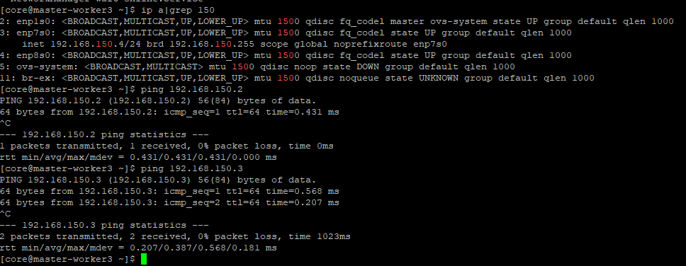
This confirms that the enp7s0 interface has been successfully configured on each of the nodes.
Setting Up a Bridge Using enp8s0 Interface
In this example, I will configure a bridge interface using a NetworkAttachmentDefiniton for interface enp8s0 on each of the nodes using MACVLAN. enp8s0 is on the same network as enp7s0. This made things easier for troubleshooting purposes (a place to run pings and curls from). Only layer-2 networking will be configured on enp8s0 (bridge) with no IP address.
The bridge will be configured to supply dynamic IP addressing through IPAM/Whereabout since no DHCP exists on this network.
The process I am following is based on:
Here is the NetworkAttachmentDefinition that will be applied. This file is called enp8s0-150Subnet-WhereAbouts.yaml.
apiVersion: k8s.cni.cncf.io/v1
kind: NetworkAttachmentDefinition
metadata:
  name: enp8s0-150subnet-whereabouts
spec:
  config: |-
    {
      "cniVersion": "0.3.1",
      "name": "macvlan-net",
      "type": "macvlan",
      "master": "enp8s0",
      "mode": "bridge",
      "ipam": {
        "type": "whereabouts",
        "range": "192.168.150.192/24"
      }
    }
oc apply -f enp8s0-150Subnet-WhereAbouts.yamlVerify that the object now exists. This resource is namespace-scoped. We will need to create the pod (next step) in this same namespace/project.
oc get net-attach-def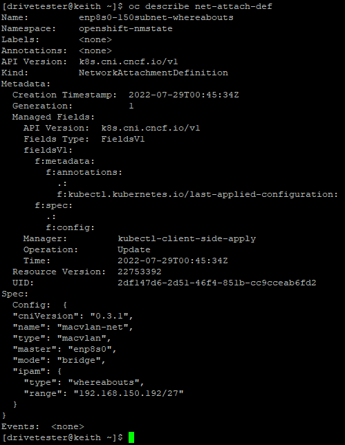
Creating HTTPD Pod on 150 Subnet Using Net-Attach-Def
To attach a pod to the net-attach-definition that was created earlier (enp8s0-150subnet-whereabouts), an annotation needs to be put into the deployment to specify that network.
For example:
metadata:
  annotations:
    k8s.v1.cni.cncf.io/networks: enp8s0-150subnet-whereabouts
Apply the following deployment. The file is called httpd-whereabouts.yaml
kind: Deployment
apiVersion: apps/v1
metadata:
  name: httpd
spec:
  replicas: 1
  selector:
    matchLabels:
      app: httpd
  template:
    metadata:
      creationTimestamp: null
      labels:
        app: httpd
        deploymentconfig: httpd
      annotations:
        k8s.v1.cni.cncf.io/networks: enp8s0-150subnet-whereabouts
    spec:
      containers:
        - name: httpd
          image: quay.io/kcalliga/httpd-8080
          ports:
            - name: httpd-port
              containerPort: 8080
              protocol: TCP
          resources: {}
          terminationMessagePath: /dev/termination-log
          terminationMessagePolicy: File
          imagePullPolicy: Always
      restartPolicy: Always
      terminationGracePeriodSeconds: 30
      dnsPolicy: ClusterFirst
      securityContext: {}
      schedulerName: default-scheduler
      imagePullSecrets: []
  strategy:
    type: RollingUpdate
    rollingUpdate:
      maxSurge: 25%
      maxUnavailable: 25%
  revisionHistoryLimit: 10
  progressDeadlineSeconds: 600
  paused: false
oc apply -f httpd-whereabouts.yamlVerify the pod exists. This pod listens on port 8080

Let's look at the YAML definition for the pod to see which IP address was assigned.
oc get po httpd-6d77c6d7bf-s57wg -o yaml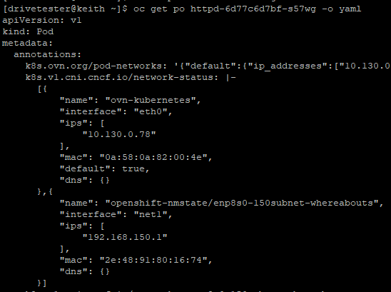
From the output above, we can see that the additional network has an interface called "net1" and the pod was assigned IP 192.168.150.1.
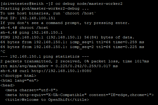
Verifying Pod Connectivity
From any of the OCP nodes, let's try to ping the IP (192.168.150.1) and run a simple curl command against port 8080.
oc debug node/master-worker2
ping 192.168.150.1
curl http://192.168.150.1:8080
The output below is abbreviated but you can see that I am able to ping the IP and the webserver responds
I hope you enjoyed this article. Much more content to follow soon.