
OpenVswitch/OVNKubernetes Primer (Part 2)
Now, we will dive into part 2 of this series which will deal more with the OVN/OVNKubernetes.
As with the first article, I am sourcing some information from the official OVN website.
 The OVN community
The GitHub repo for OVNKubernetes
 ovn-org
Lastly, I will re-use some diagrams based on a presentation from Red Hat.

I would recommend reading part 1 of this series which covers the basics in regards to OpenVSwitch.
This is the description of OVN right from the OVN website.
OVN (Open Virtual Network) is a series of daemons for the Open vSwitch that translate virtual network configurations into OpenFlow. OVN is licensed under the open source Apache 2 license.
OVN provides a higher-layer of abstraction than Open vSwitch, working with logical routers and logical switches, rather than flows. OVN is intended to be used by cloud management software (CMS). For details about the architecture of OVN, see the ovn-architecture manpage. Some high-level features offered by OVN include:
Distributed virtual routers
Distributed logical switches
Access Control Lists
DHCP
DNS server
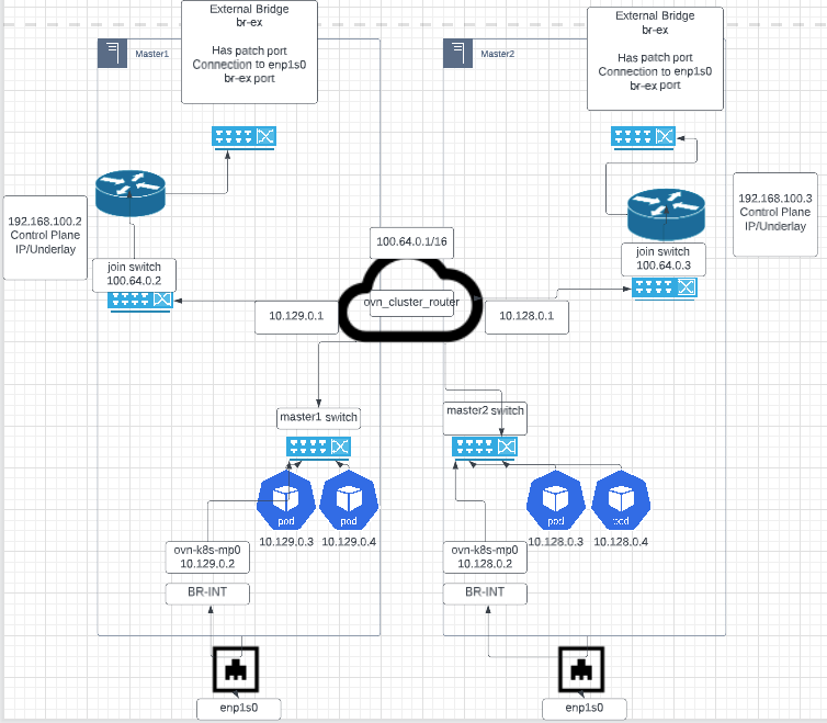
Let's start with a diagram that shows how the OVNKubernetes networking is setup in relation to OpenVswitch. This is taken from the presentation link shown above.
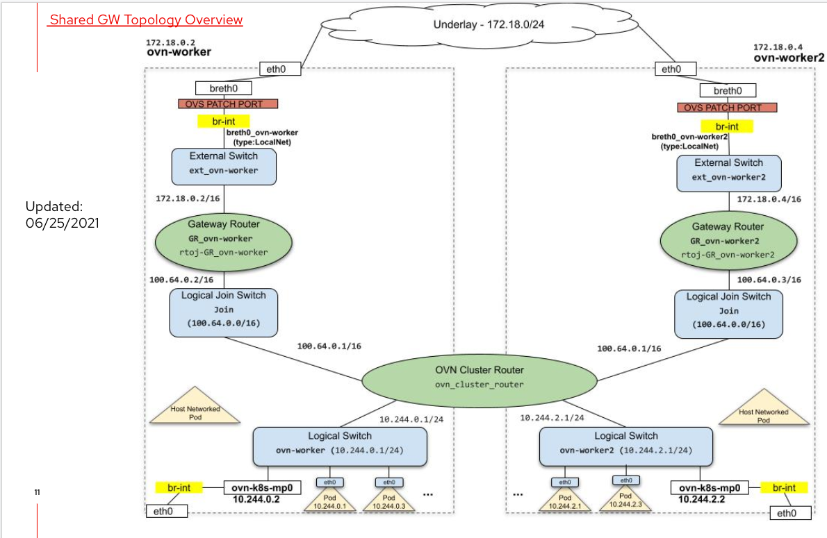
This diagram doesn't match my cluster exactly but it is enough information so that we can construct a similar chart using OVN tooling later.
Let's look at some information that is presented in the OVN configuration.
On the OCP cluster, run the following commands:
oc project openshift-ovn-kubernetes
# To get current leader information
oc describe cm ovn-kubernetes-master
# To get name of pod to connect to in order to run OVN tooling
oc get po|grep ovnkube-master|grep <leaderfromlaststep>
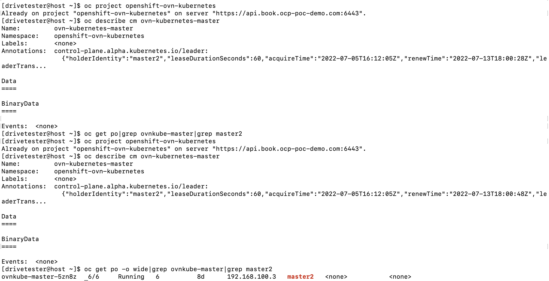
Based on the above output, the ovnkubernetes-master-holder is master2. If we look for the name of the ovnkube-master pod that is running on master2, it is called ovnkube-master-5zn8z
Let's now connect to this pod to run some OVN commands.
oc rsh ovnkube-master-5zn8z

There are two commands that will be used for this demonstration. They are ovn-nbctl and ovn-sbctl.
ovn-nbctl shows the logical components that make up OVN such as logical routers, switches, and port information (IP and mac addresses of connected pods), and NAT (Network Address Translation) information. Here is a sample of the output.
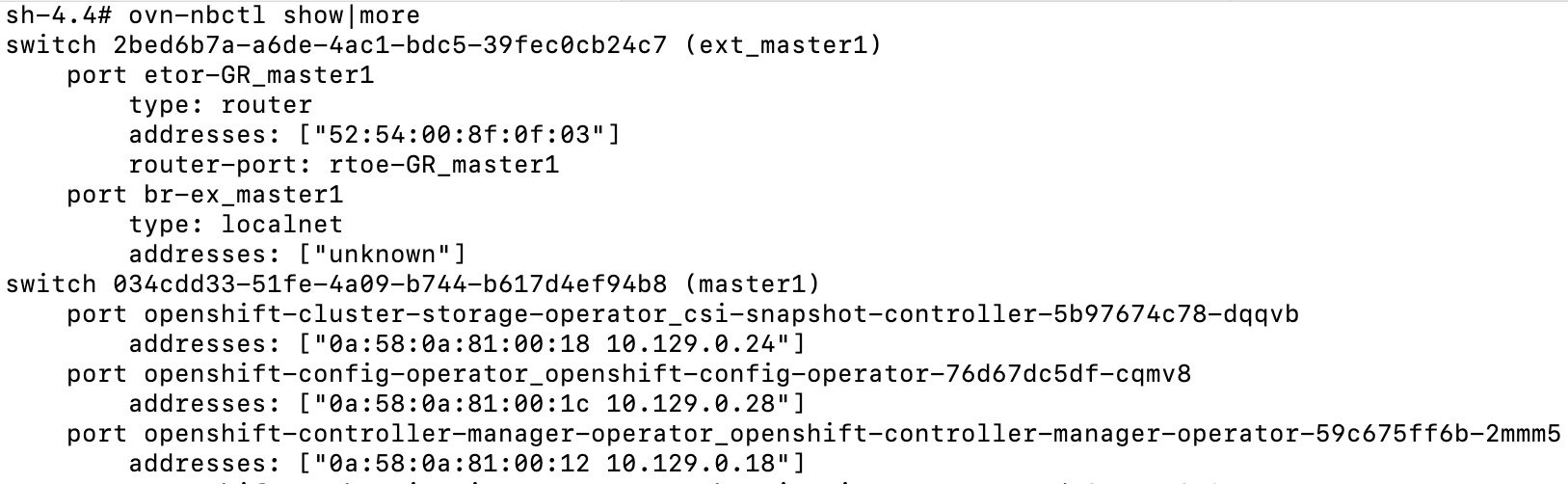
This part of the output shows the ext_master1 switch and the master1 switch. The master1 switch corresponds to the same switch that we used in the OVS demonstration (part 1 of this article). If you recall, the 10.129.0.2 IP originated there.

The ovn_cluster_router is where 10.129.0.1 lives and Geneve tunneling is used to reach down to the OVS switch which resides on master1.
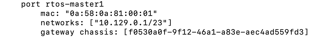
Let's now look at the router output that shows as a result of the ovn-nbctl show command. This output will show some connected ports but also shows the NAT entries that need be traversed to reach a destination pod.

In the example shown above, we see that 10.129.0.32 is reachable via 192.168.100.2 which is the master1 server.
The ovn-sbctl command more downstream information such as chassis name, corresponding server, and the actual port-bindings. The port-binding name is the same name as the pod.
See the abbreviated output below
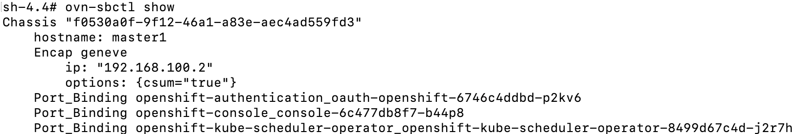
This shows the pods that are reachable over the Geneve tunnel to master1/192.168.100.2.
If this information, does not click yet, that's ok. We will now make our own diagram. It won't look exactly the same as the one on the presentation (I'm not that good at network diagrams), but I will try my best. LucidChart is being used for this.
Network Diagram Exercise
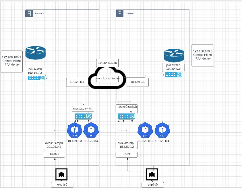
Here, we will use OVN tooling to construct a network diagram based on my cluster.
I will show all output (all masters and workers) in the commands but will only show master1 and master2 in the network diagram.
- Let's get a list of all switches and routers.
# Get list of switches
ovn-nbctl ls-list
# Get list of routers
ovn-nbctl lr-list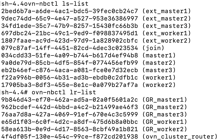
We have the following switches
# Switches that connect to external bridge from each node. IE: ethernet #interface on control-plane/underlayer network
ext_master1
ext_master2
ext_master3
ext_worker1
ext_worker2
# join is the switch that connects to the gateway router on each node
join
# these switches are are mostly synonymous with the switches we looked # at with the OVS exercise.  These connect to both the join switch and #external switches
master1
master2
master3
worker1
worker2
Here is a list of routers
# Gateway routers which connect join and external networks.  Also keeps # track of NAT information
GR_master1
GR_master2
GR_master3
GR_worker1
GR_worker2
# Connects to individual node switches and join switch.  Hosts the  #100.64.0.1 IP which is comms used to join switch.
ovn_cluster_router
2. Starting from the bottom of the original diagram, we need the name of the physical interface on the nodes, and the subnets assigned to pods on master1/master2.
enp1s0 is the physical interface
If we don't remember the pod subnets for master1 and master2, run the following command
ovn-nbctl show ovn_cluster_router|grep -A2 -e master1 -e master2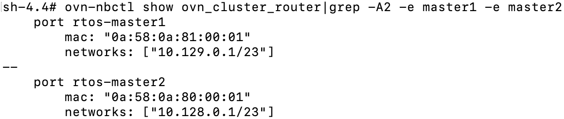
The subnet for master1 pods is 10.129.0.0/23 and master2 is 10.128.0.0/23
I am using generic pod IPs in this example. 10.129.0.3/10.129.0.4 for master1 and 10.128.0.3/10.128.0.4 for master2.
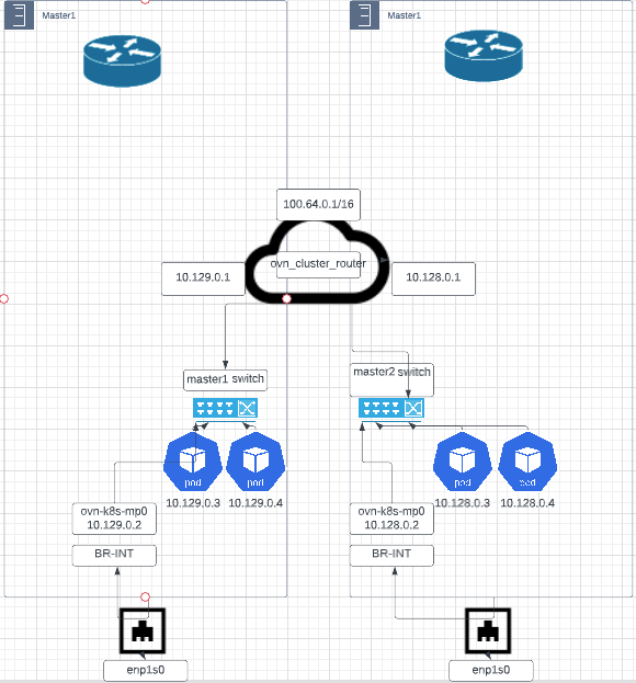
Above the ovn_cluster_router is the join switch on each of the nodes.
3. Let's look at the ports, IP addressing, and route tables on the ovn_cluster router and the join switches on master1/master2 to continue working on this diagram.
# Show ports on logical join switch
ovn-nbctl show join
# Show ports on ovn_cluster_router and pod network endpoints
ovn-nbctl show ovn_cluster_router
# show route table for ovn_cluster_router
ovn-nbctl lr-route-list ovn_cluster_router
Join Switch
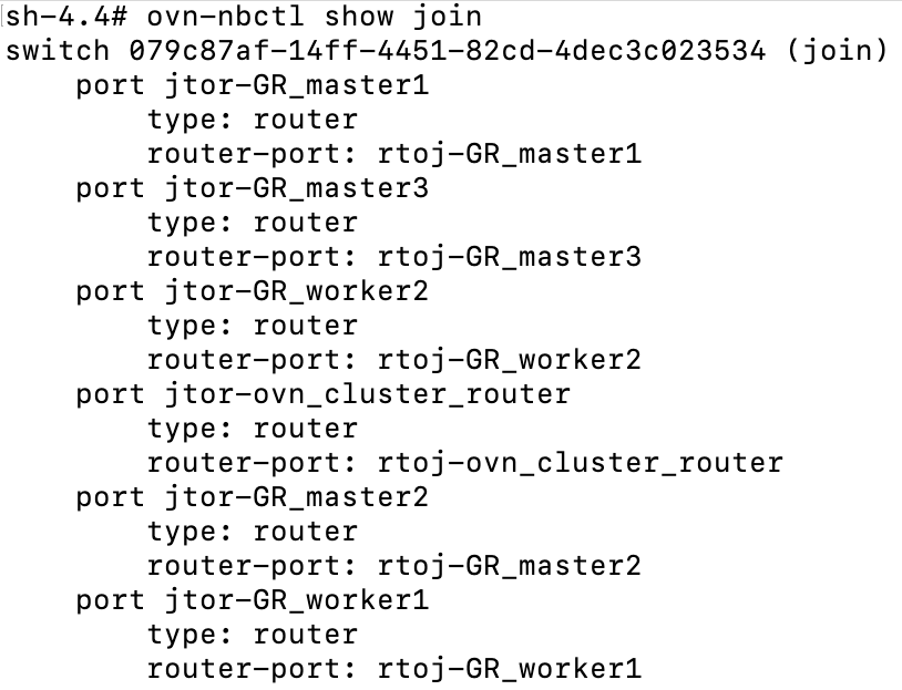
We can see the naming convention called jtor and rtoj. This is referring to join-to-router (jtor) and router-to-join (rtoj). The join switch has connections to each nodes gateway router and the ovn_cluster_router.
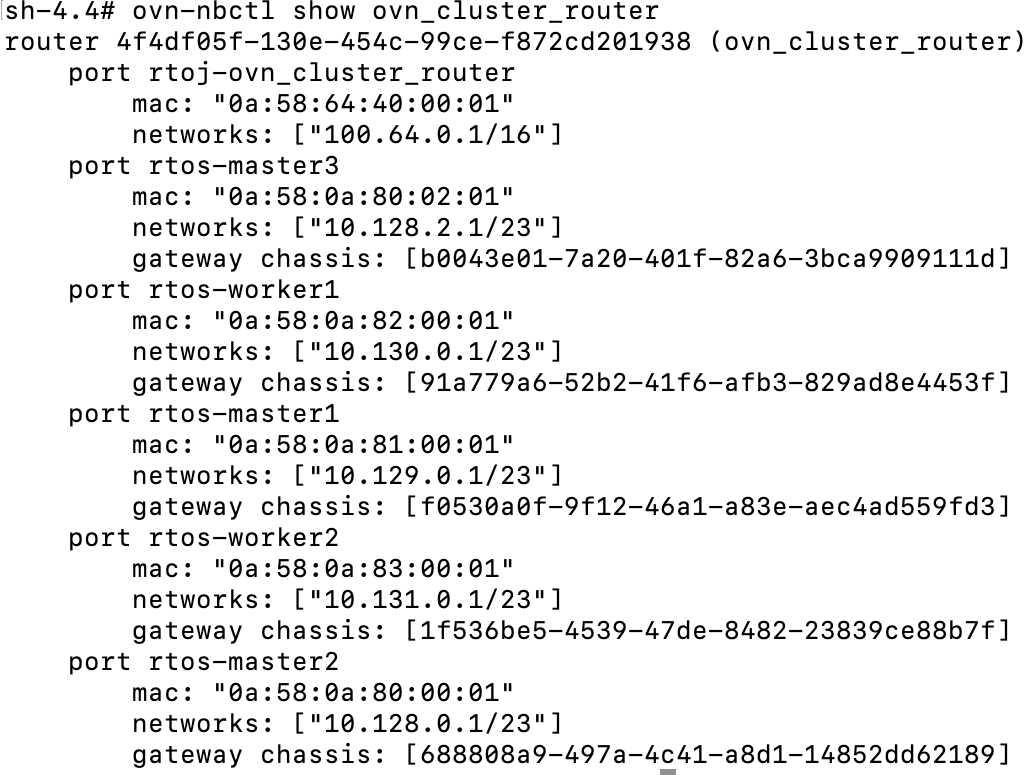
The show command run on the ovn_cluster_router (above) uses the rtos naming convention (router-to-switch) and rtoj (router-to-join). It shows the ovn_cluster_router endpoint (100.64.0.1/16) reachable and each of the pod IP networks.
Route table from ovn_cluster_router
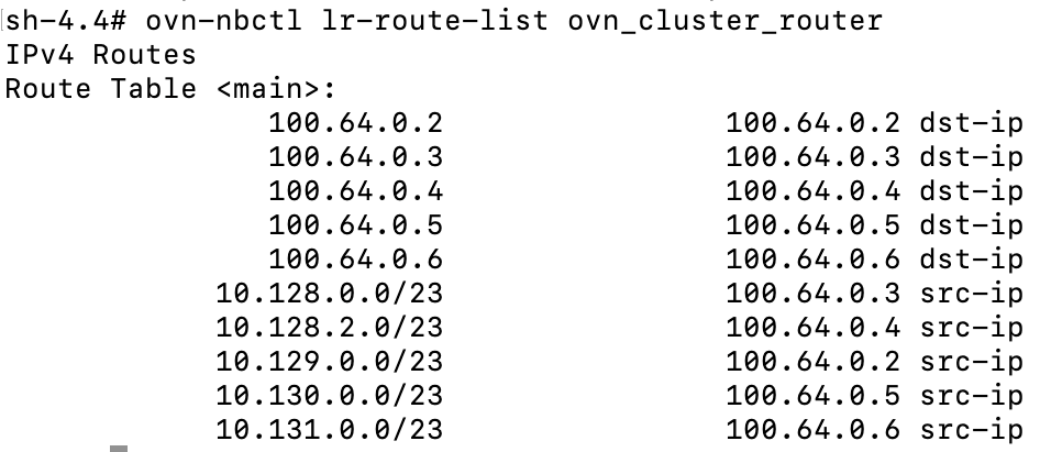
For the two nodes we are working with (master1 and master2), this tells us that 10.129.0.0/23 (master1) is reachable through the 100.64.0.2 which is the master1's connection to the join switch.
To confirm
ovn-nbctl show GR_master1|grep -B3 100.64
For master2, we can do the same. 10.128.0.0/23 is reachable from 100.64.0.3 connection on join switch.
ovn-nbctl show GR_master2|grep -B3 100.64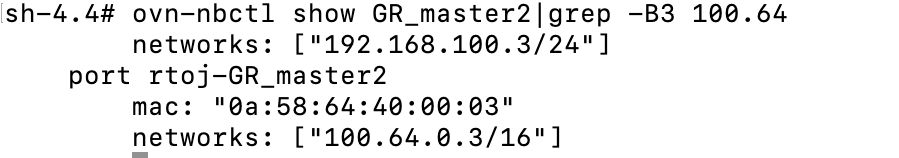
Let's add the join switch and gateway router to our diagram
4. The last couple pieces of the picture involve the external switch. The naming is either etor (external-to-router) or rtoe (router-to-external) depending on which device your are coming from.
Let's discover some information between the gateway router and external switch for master1/master2.
# Show routes from gateway router
ovn-nbctl lr-route-list GR_master1
# Same for master2
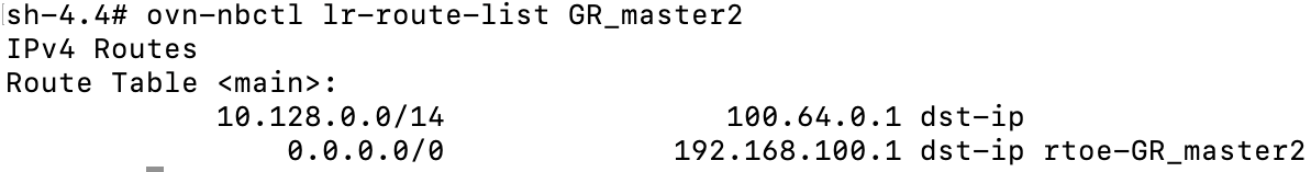
ovn-nbctl lr-route-list GR_master2
# Show conencted external ports on master1 and master2 GR router
ovn-nbctl show GR_master1|grep -A2 rtoe-GR_master1
# Same for master2
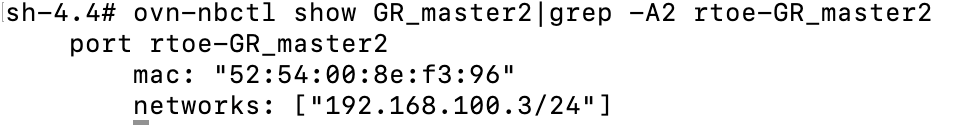
ovn-nbctl show GR_master2|grep -A2 rtoe-GR_master2

From this output, we can tell that GR_master1 router uses the ovn_cluster_router (100.64.0.1) path for packets destined to 10.128.0.0/14 pod network and anything else goes to the main gateway on control-plane network (192.168.100.1)
This is similar on master2
These last outputs show the rtoe (router-to-external) endpoint that are reachable through the rtoe-GR_master(1/2) ports. 192.168.100.2 is the main IP for master1 and 192.168.100.3 is the main IP for master2.

Let's finish the last couple of pieces of this diagram.
The external bridge as defined in OVN is the same (br-ex) bridge that we dealt with on for the OVS exercises (part 1).
-It has a connection to a patch port (patch-br-ex-<node>-to-br-int)which is used for external traffic coming into the cluster (mostly to pod networks).
-For outgoing traffic, this bridge is used for communications that go outside of the cluster (IE: internet or other upstream network).
-It is used for any other connection on the node (IE: enp1s0 or eth0)
-Lastly, it also routes traffic to the service network.
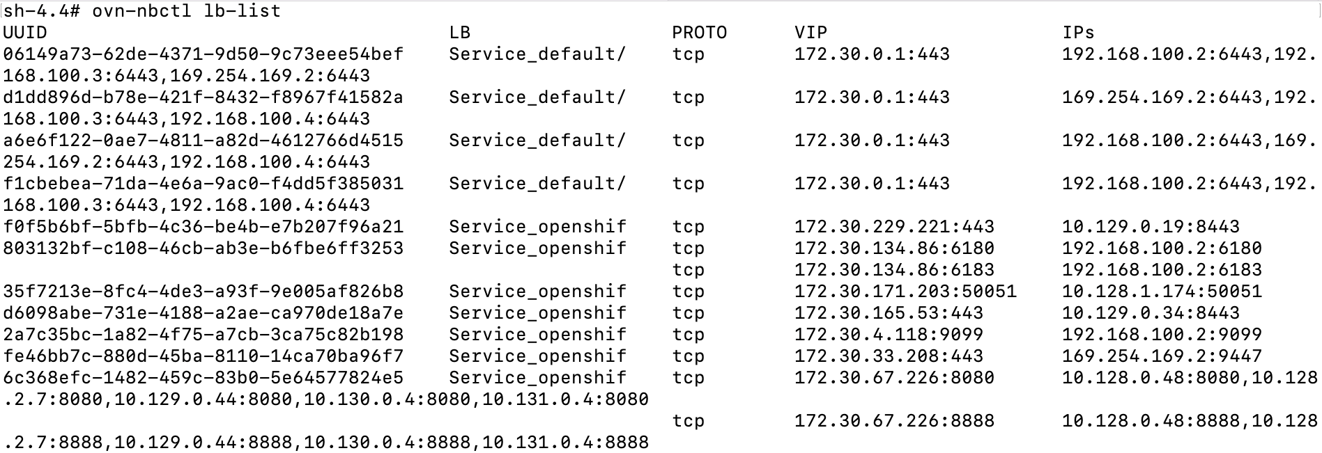
One last command I want to show for completeness is how to view the service IPs (load-balancer) and endpoints from OVN tooling.
ovn-nbctl lb-listThis output is abbreviated
We may dive into this some more in follow-on blog posts.
Hope you enjoyed. Much more to come.